| User Guide | API | Demos | Installation Guide | Search |
OMINAS User Guide
Open-source Multiple INstrument Analysis Software
Reading and Writing Data files
Reading and Writing Ancillary Information
Coordinate Transformation Variations
6. Working With OMINAS Objects
A. Object Descriptor Naming Conventions
C. Cloning, Copying, and Freeing Descriptors
Composite Transformation Routines
8. Graphical Interface to OMINAS (GRIM)
A. Interface to GRIM Data (INGRID)
Introduction
OMINAS is an IDL-based software environment for the reduction and analysis of data taken by any space-based or planet-based system. It was conceived and written by Joseph Spitale (jnspitale@psi.edu). Other contributors include Vance Haemmerle, Matthew Tiscareno, John Weiss, Daiana DiNino, Paulo Penteado, Jackie Ryan and Mark Moretto. Funding for its initial development was provided by the Cassini mission.
Functional requirements
OMINAS development is guided by the following functional requirements:
Portability
OMINAS should operate on as many platforms as possible. This requirement is easily implemented using IDL. Historically, OMINAS has been used on Alpha/OSF, Sun/Solaris, PC/Linux and Mac/OS X. At present, it is running on PC/Linux, Mac/OS X, and PC/Windows.
Speed
IDL's portability is achieved via the interpretation of a machine-independent pseudocode, which significantly affects its performance. Therefore, care must be taken to use vectorized operations where necessary to optimize efficiency. OMINAS programs are often comparable in speed to analogous code written in C, but there is a memory cost due to the use of of large arrays.
Modularity
OMINAS obeys object-oriented software concepts, so that it is highly modular and relatively easy to modify. Although IDL directly provides for an object-oriented architecture, that capability is only partially used in OMINAS, for reasons discussed below.
Generality
OMINAS itself does not contain any code that is dependent upon the particular instrument that generated the input data, or upon the organization of the file in which the data resides. Because IDL compiles code dynamically, this requirement is met in OMINAS by allowing for external user-written configuration code that contains all of the specifics of a particular data source.
Scripting
OMINAS maintain a lowest-level user interface that operates from a command line so that analyses may be constructed as command scripts. Such a capability is necessary in order for jobs to be performed in batch mode with no user intervention. OMINAS contains a command-level user interface known as `PG <./com/pg/index.html>`, which consists of a number of IDL programs. Those programs may be combined into IDL batch files and run autonomously. There is also a graphical interface called `GRIM <./gr/index.html>` (Graphical Interface to OMINAS).
Choice of IDL as a platform for OMINAS
Prior to OMINAS' development, the above requirements were identified as necessary conditions to justify the development of a new tool. Any platform that fails to meet any of the requirements is ruled out. To the best of our knowledge, IDL is the platform that best meets the above requirements. Indeed, it may be the only one.
IDL's primary drawback is that it requires a relatively expensive license to access the full version. To mitigate this issue we (a) endeavor to keep OMINAS compatible with the earliest possible version of IDL so that users do not have to continually pay to update IDL licenses (8.2.3 is my current version and I have no desire to ever upgrade); and (b) provide a run-time virtual-machine version that does not require an IDL license, but is somewhat less functional. Moreover, much of OMINAS works in the seven-minute IDL demo mode. In that mode, files cannot be written, but files may be read, the interactive tools work, and batch files may be executed, so in some circumstances that is a viable option.
It is possible that a future version of IDL may entice us to upgrade, but it would need to offer a significant benefit. One hypothetical IDL improvement that could motivate an upgrade would be to allow object methods to be called for arrays of objects. That might allow a full IDL-object implementation of OMINAS, which would have some important benefits benefits (see Sec. [[]]).
Another alternative under consideration is the GNU Data Language (GDL), an open-source IDL compiler.
Architecture
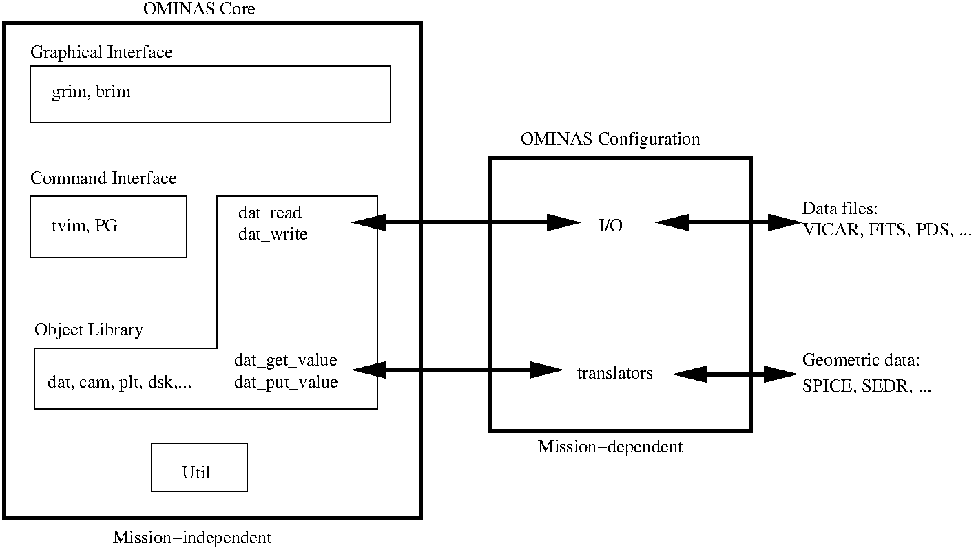
The following diagram illustrates the relationships among the various components of an OMINAS installation.
The core OMINAS code is completely independent of the source of the data and the type of file in which it is stored. Those details are configured based on the intended purpose of a particular OMINAS installation. For example, the Cassini ISS installation contains configuration code that reads and writes VICAR image files and SPICE kernels.
The separation between the data processing and I/O is maintained by OMINAS' DATA object. DATA uses application-specific configuration tables to determine how to transform ancillary data from external sources into the standard objects recognized in OMINAS.
The OMINAS object library defines and manipulates the the basic objects used to describe the various entities -- cameras, planets, rings, etc., -- of interest to the user.
The typical OMINAS user will operate at the command level, which consists of the image display program `TVIM`, the NV I/O commands DAT_READ and DAT_WRITE, and a set of programs based on the underlying object library and utility routines referred to as `PG <./com/pg/index.html>`.
There is also a graphical interface to OMINAS is called `GRIM <./gr/index.html>`. Although it is designed to be used along with the command line like a fancy TVIM, GRIM may be used on its own.
Getting started
Historically OMINAS (technically MINAS) users simply played around with the demo scripts and adapted them to their purposes. We have been working to better document the system, but the demo scripts are still a good way to get started. See the OMINAS README for more information.
The OMINAS object library implements an object-oriented description of various geometrical objects to be used by higher level programs. A specific object, e.g., CAMERA, is built as a subclass of a more general object, like BODY. Information about a particular object is stored in an IDL object referred to as an object descriptor (e.g., camera descriptor, planet descriptor).
One of the primary drivers in the object library is speed. Unless carefully written, IDL code can be extremely slow. Routines in the object library use vector operations to achieve performance comparable to analogous routines written in C, though they generally use more memory. The use of massive array operations in writing efficient IDL code is discussed later in this document.
The object descriptor was originally implemented as a structure. Structures provide very fast dereferencing compared to IDL objects because a loop is not required. Also, OMINAS' original development occurred at a time when the IDL object type was relatively new, so structures offered a more stable data type, allowing OMINAS to remain backward compatible to IDL 5.3.
In the current implementation of OMINAS, the object descriptor is a true IDL object. This allows various programs to operate on the same heap object, but it forces the object library routines to perform a loop to dereference an array of descriptors (i.e., convert between arrays of pointers and arrays of structures), so that internal operations can be performed efficiently. The dereferencing is performed using the COR_DEREFERENCE and COR_REREFERENCE methods. Object methods typically perform that conversion once on the inputs, and then again on the outputs. In between, they operate directly on the object structures.
Although the object library is based on IDL objects, the methods are implemented as regular IDL procedures and functions rather than object methods because IDL object methods cannot operate on arrays of objects. In other words, in the call "xd.method()", xd must be a scalar. That constraint is too restrictive for OMINAS because it forces external loops to be used, preventing more efficient internal vectorized operations. Also, it would force the user to write loops on the command line. For example:
IDL> for i=0, n_elements(xd)-1 do print, xd.name()
vs.
IDL> print, cor_name(xd)
One obvious drawback with OMINAS' method scheme is that it is left to the programmer to respect the object-oriented rules of the library, whereas IDL objects leave the programmer no choice. The importance of working within the object-oriented framework cannot be overstressed. Its compromise can only end in sadness and pain.
Another drawback to this procedure-based method scheme is that the caller must know the classes of the object methods that it uses because of the prefix conventions used to avoid conflicts. This makes it more difficult to modify the organization of the object library without impacting use applications.
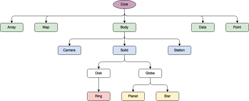
The following diagram illustrates the relationships among the existing OMINAS object classes.
Below is a table with a brief summary of each class. For more information on a particular class, see its documentation.
Name | Description | Abbrev |
CORE | Superclass of all other classes; contains information and functionality that is meant to be common to all classes. It keeps track of the name of an object, the name of the user, and a 'task list', which records the names of routines that have modified the descriptor. | COR |
DATA | Describes and manages a data set, including file I/O and translation of geometry data. | DAT |
POINT | Describes and manages arrays of points. | PNT |
ARRAY | Describes arrays of points fixed to rigid bodies. | ARR |
BODY | Describes the position and orientation of rigid bodies. | BOD |
SOLID | Manages common attributes of three-dimensional bodies: photometric properties, mass, etc. | SLD |
GLOBE | Describes the shapes of planet-like objects. Currently, it describes a triaxial ellipsoid, but this may be generalized in the future. | GLB |
DISK | Describes the shapes of objects that are disk-like. Currently, it describes a perfectly flat object with inner and outer edges specified as Keplerian ellipses, but this may be generalized in the future. | DSK |
PLANET | Describes substellar objects like planets and satellites. | PLT |
STAR | Describes stars. | STR |
RING | Describes rings in orbit about a primary body. | RNG |
CAMERA | Describes instruments that produce raster images. | CAM |
MAP | Describes map projections. | MAP |
STATION | Describes bodies that are rigidly attached to other bodies. | STN |
CORE
CORE is a superclass of all other classes and contains information and functionality that is meant to be common to all classes. It keeps track of the name of an object, the name of the user, and a 'task list', which records the names of routines that have modified the descriptor.
Data Objects
Task List | The core descriptor maintains a list of the names of every program that has modified this descriptor. A program that modifies the descriptor should call COR_ADD_TASK to add its name to the list immediately after it has modified the descriptor. Tasks cannot be removed from the list. |
User Data | The core descriptor maintains a list of user-generated named data objects. |
Core Descriptor | The core descriptor is the class structure for the CORE class. See OMINAS_CORE__DEFINE. |
CORE -> DATA
The DATA object describes a data set and how it is accessed and manipulated. It includes an associated user-defined header array and a "detached header" (see below). Data arrays may be maintained in various ways: load immediately, load when accessed, load only when accessed, store compressed, load only select samples, etc. The data descriptor maintains a history of the data array and header, so changes may be undone. The data object also describes how geometry descriptors are managed.
Data sets are read and written via DAT_READ and DAT_WRITE. These program use I/O routines specified in the I/O table to perform their functions. DAT_READ also reads the translators tables and concatenates them into a master table for a given DATA descriptor. DAT_GET_VALUE and DAT_SET_VALUE use the master translators table to read and write geometry descriptors. This system isolates the data arrays from the user-configured source, and the geometry from its user-configured source.
The purpose of the DATA I/O system is to maintain the separation between the core OMINAS data processing code and the external data sources. Most of the functionality of the I/O system is devoted to parsing the configuration tables and making sure that the appropriate user-specified routines are called.
The DATA object explicitly implements the OMINAS requirement of general applicability, which encompasses the following two principles:
OMINAS maintains the clear distinction between the code that is dependent upon the circumstances of the data collection and archival process and the code that performs analysis on the data set. For example, a program that computes the limb of a planet should not contain explicit code that attempts to read SPICE kernels in order to determine the encounter geometry. Under OMINAS, this information is obtained by user-written translators and provided as an input to the program. The DATA object provides the framework for this process.
Programs written under OMINAS take their input data in the form of IDL arrays, so the organization of the original data file is irrelevant. The DATA object provides a mechanism for detecting file types using the appropriate user-written routines to read and write data files.
Under OMINAS, data files are read using the DAT_READ function. DAT_READ looks up the names of the input and output functions in the I/O table and uses the input function to read the data file. Then it calls DAT_CREATE_DESCRIPTORS to create one or more data descriptors.
Data files are written using the DAT_WRITE procedure, which calls the output function in the data descriptor to write the data.
Ancillary information (e.g., a state vector) is input and output using the DAT_GET_VALUE and DAT_PUT_VALUE routines. DAT_GET_VALUE calls user- written procedures called a translators that know how to obtain the requested information (keywords). The translator would be different depending on spacecraft mission and the source of the data (e.g. SEDR, SPICE, etc.).
In all OMINAS configuration tables, lines beginning with '#' are ignored. Lines can be continued across multiple lines using a backslash '\'. Table file names are specified using environment variables, as given below. Multiple table are specified using colons as delimiters. In that case all such tables are concatenated into a master table. Below is an explanation of each configuration table.
The name of the filetype detectors table is taken from the NV_FTP_DETECT environment variable. The table has three columns: the name of the detector function, the filetype string, and the action respectively. To detect the filetype, each function in the table is called with the filename as the only argument until true is returned. If the action is 'IGNORE', DAT_READ aborts the operation and returns without reading a file. Otherwise, the filetype string corresponding to that entry in the table is used in the data descriptor.
Example:
# detector fn filetype action
detect_vicar VICAR read
detect_fits FITS read
The name of the I/O table is taken from the NV_IO environment variable. The table has four columns: The first column is the filetype string as given in the filetype detectors table; the second two columns give the names of the input and output functions respectively; the fourth column gives name of a keyword function.
Example:
Filetype input function output function keyword function
VICAR dh_read_vicar dh_write_vicar dh_vicpar
FITS dh_read_fits dh_write_fits dh_sxpar
DAT_READ ad DAT_WRITE use the output functions for file I/O. The definitions of those functions are as follows:
function <input_fn>, $
dd, $ ; Data descriptor; contains
; filename,possibly scene geometry
header, $ ; Output; header array
dim, $ ; Output; dimensions of data array
type, $ ; Output; data type
min, max, $ ; Output; data extrema
abscissa=abscissa, $ ; Output; optional abscissa array
gff=gff, $ ; Output: optional generic file
; format descriptor
nodata=nodata, $ ; if set, no data are read
sample=sample, $ ; Requested data samples
returned_samples=returned_samples
; Output: optional samples actually
; returned
pro <output_fn>, $
dd, $ ; Data descriptor; contains default
; filename, data, abscissa, header;
; possibly scene geometry
filename, $ ; Filename
data, $ ; Data array
header, $ ; Header array
abscissa=abscissa, $ ; Optional abscissa array
nodata=nodata ; if set, no data are written
The name of the instrument detectors table is taken from the NV_INS_DETECT environment variable. The table has two columns. The first column is the name of a detector function and the second is the a file type string. Only functions whose file type in the table matches that of the data file are called. To detect the instrument, each function is called with the data descriptor as the only argument until a string other than the null string is returned. This returned string is the taken as the instrument name.
Example:
# detector fn filetype
detect_vgr_iss VICAR
detect_cas_iss VICAR
detect_mirac FITS
detect_gll_ssi VICAR
The name of the translators table is taken from the NV_TRANSLATORS environment variable. The table has four columns. The first column is the instrument string as returned by the instrument detector function. The second two columns give the names of the input and output translators respectively. The fourth column gives arguments for the translator functions in the form of keyword=value pairs. Each of the translator columns may contain more than one translator for each instrument string using multiple lines as shown in the example. Note the use of dashes to mark blank columns.
Keyword inputs in the translators table use a syntax similar to that used in calls to IDL routines. Note the examples in the table below. The keywords on a given line are available to both the input and the output translators specified on that line. They are passed to the translators with no processing by OMINAS.
Translator function are defined as follows (The input translator returns a list of object descriptors):
function <input_translator>, $
dd, $ ; Data descriptor
keyword, $ ; Describes data being requested
values=values, $ ; Current list of value returned by
; previous translators in the table
status=status ; Output: 0 = success, -1 = failure.
pro <output_translator>, $
dd, $ ; Data descriptor
keyword, $ ; Describes data being written
value, $ ; Descriptors to write
status=status ; Output: 0 = success, -1 = failure.
Example:
# instrument input output args
# string translator translator
COMMON dh_std_input dh_std_output
- station_input -
- array_input -
- ring_input -
- orb_input - suffix=-orb
VGR1_ISSNA dh_vgr_issna_input dh_vgr_issna_output
- strcat_vgr_issna_input -
VGR1_ISSWA dh_vgr_issna_input dh_vgr_issna_output
- strcat_vgr_issna_input -
VGR2_ISSNA dh_vgr_issna_input dh_vgr_issna_output
- strcat_vgr_issna_input -
VGR2_ISSWA dh_vgr_issna_input dh_vgr_issna_output
- strcat_vgr_issna_input -
MIRAC dh_mirac_input dh_mirac_output
GLL_SSI dh_gll_ssi_input dh_gll_ssi_output
GLL_NIMS dh_gll_nims_input dh_gll_nims_output
CAS_ISSWA dh_std_input dh_std_output format=CAS
- ring_input -
- strcat_gsc_input - /j2000
Translators are called in the order they appear in the table, unless associated with the COMMON instrument string. Those translators are always called first. Any translators associated with the DEFAULT instrument are called only if no other instrument strings are matched.
The name of the transforms table is taken from the NV_TRANSFORMS environment variable. The table has three columns. The first column is the instrument string as returned by the instrument detector function. The second two columns give the names of the input and output transforms respectively. Each of the translator columns may contain more than one transform function for each instrument string using multiple lines as shown in the example. Note the use of dashes to mark blank columns.
If the NV_TRANSFORMS variable is undefined, then a transforms table is not used.
Example:
# instrument input output
# string transform transform
CAS_ISSWA cas_delut cas_relut
A detached header is a text file used to store ancillary information for a data set in a standard, machine-independent format. Detached headers can be useful (1) when there is no other standard format available for storing the ancillary data, as would be the case for a map projection generated by OMINAS; or (2) for isolating one's updates from all external sources. In the latter case, all of the ancillary information, regardless of its original source, would be stored in a detached header, along with all updates to that data. Different analyses on the same data set can be pursued using two different detached headers, for example. Also, the detached header keeps track of the update history.
A detached header consists of two or more sections, separated by a line containing the section name enclosed in angle brackets, i.e., '<updates>'. The first section, which starts at the first line of the detached header and is not preceded by a section label, contains global information such as the current history number of the file. The second section, labeled '<updates>', contains update information. Any number of later sections may be added by the user.
The syntax for each line of the detached header is as follows:
keyword(i)[o]{h} = value / comment
'keyword' and 'value' are strings of any length consisting of any characters except for "*", "(", ")", "[", "]", "{", "}", "<", ">", and "/".If 'value' represents a string value, then it must be enclosed in single quotes. 'comment' is a string of any length consisting of any characters.
'i' is the element index and denotes elements of an array.
'o' is the object index and denotes different objects described by the same keyword parameters.
'h' is the history index and denotes different updates of a keyword parameter.
The element, object, and history indices default to 0 if not present.
Examples:
The following examples illustrate the the above syntax:
cam_name = 'VGR1_ISS_NA' / i=0, o=0, h=0
cam_name(1) = 'VGR1_ISS_NA' / i=1, o=0, h=0
cam_name[2] = 'VGR1_ISS_NA' / i=0, o=2, h=0
cam_name(1){3} = 'VGR1_ISS_NA' / i=1, o=0, h=3
The following keywords are reserved:
history Value of greatest history index.
utime Julian date of most recent update for a particular history index.
updates Separates global section from the update section.
Detached headers are read and written in OMINAS using the translators DH_STD_INPUT and DH_STD_OUTPUT. These translators read or write geometry descriptor data to or from a detached header. The keywords used in the detached header are derived from the object class names and object structure field names.
The POINT object describes an array of points. A single POINT object contains an array of image points and their corresponding inertial vectors, if applicable. In addition, there is a flag array providing a bit-mask for each point.
The points array is (2,nv,nt) and the vectors array is (nv,3,nt), where nv is the number of points or vectors and nt is the number of timesteps. There is a one-to-one correspondence between image points and inertial vectors.
The flags array is long (nv,nt), with one flag word for each point. This allows for 32 1-bit flags per point. The flag masks are defined in pgs_include.pro.
The data array and tags are determined by the program. Generally, the data array is (nv,nd) or (nv,nt,nd), where nd is the number of different data values per point. The tags array is generally a string array (nd), whose purpose is to allow other programs to find these output values without requiring the user to deal with long argument lists.
CORE -> BODY
The BODY object class describes the position and orientation of a rigid body in space. It is an immediate subclass of CORE. Below are explanations of its coordinate systems and data objects.
Coordinate Systems
Inertial | Cartesian coordinate system used as the celestial reference frame. |
Body | Cartesian coordinate system centered on and fixed to the body. |
Radec | Polar coordinate system centered on and fixed to the body. Vectors are given as [ra, dec, r], where ra = right ascension, dec = declination, and r = radial distance. This is a surface coordinate system. |
Data Objects
Orientation Matrix | The orientation matrix transforms vectors given in the body coordinate system to vectors given in the inertial coordinate system (using the IDL ## matrix operator). Its form is: b0x b1x b2x b0y b1y b2y b0z b1z b2z, where the body axis vectors are b0=[b0x,b0y,b0z], b1=[b1x,b1y,b1z], and b2=[b2x,b2y,b2z], with components given with respect to the inertial system. b2 | | / b1 | / |/ ------- b0 The interpretation of the body coordinate axes depends on the superclass of of which it is a part. |
Position Vector | The position vector gives the position of the body, with components in the inertial coordinate system. |
Body Descriptor | The body descriptor is the class structure for the BODY class. See OMINAS_BODY__DEFINE. |
Methods are provided to transform between adjacent coordinate systems, e.g., inertial<-->body, body<-->radec. The basic methods transform pure vectors (i.e.,they perform rotations). However, two alternate forms are provided to transform position and velocity vectors. Those variants include a translation in addition to the rotation. They are identical; separate methods are provided for clarity.
CORE -> BODY -> CAMERA
The CAMERA object class describes instruments that produce raster images. Linear, radial and polynomial distortion models are built in, but any distortion model may be specified (actually the polynomial distortion model is currently incomplete). CAMERA is an immediate subclass of BODY.
Coordinate Systems
Focal | Cartesian coordinate system specifying locations in the focal plane as (p,q), where p and q are given in radians, and the distance from the origin to the point (p,q) is equal to the angle between the optic axis and a vector from the camera position to the point. |
Image | Cartesian coordinate system specifying locations in a two-dimensional image as (x,y), with origin (0,0) at the lower left corner (minimum sample, maximum line) of the image and x and y increasing in the increasing sample and decreasing line directions, respectively. |
Data Objects
Orientation Matrix | The orientation matrix is inherited from BODY. The b1 axis corresponds to the camera optic axis and the b0 and b2 axes points in the image x and y directions respectively. b2 = image y direction | | / b1 = optic axis | / |/ ------- b0 = image x direction |
Position Vector | The position vector is inherited from BODY. It gives the position of the camera with respect to the inertial coordinate system. |
Camera Descriptor | The camera descriptor is the class structure for the CAMERA class. See OMINAS_CAMERA__DEFINE. |
CORE -> BODY -> SOLID
The SOLID object class describes common attributes of three-dimensional bodies. It is an immediate subclass of BODY.
Data Objects
Orientation Matrix | The orientation matrix is inherited from BODY. The b2 axis corresponds to latitude=pi/2 and the b0 axis corresponds to longitude=0, as shown. b2 --> latitude = pi/2 | | / b1 | / |/ ------- b0 --> longitude = 0 |
Position Vector | The position vector is inherited from BODY. It gives the position of the body center with respect to the inertial coordinate system. |
Solid Descriptor | The solid descriptor is the class structure for the SOLID class. See OMINAS_SOLID__DEFINE. |
CORE -> BODY -> SOLID -> GLOBE
The GLOBE object class describes the shapes of planet-like objects. Currently, it describes a triaxial ellipsoid, but this may be generalized in the future. It is an immediate subclass of SOLID.
Coordinate Systems
Globe | Rotating spherical coordinate system defined with respect to the surface of the body. Vectors are given as [planetocentric latitude, east planetocentric longitude, altitude from local radius]. The prime meridian is defined by the b0 body axis (see diagram below). This longitude reference is not constrained by the glb package. The 'lref' field in the globe descriptor can be used to identify the particular longitude system so that other programs can perform conversions among longitude systems if desired. This is a surface coordinate system. |
Graphic | Analogous to the globe coordinate system except that latitudes and longitudes are planetographic. |
Local | Rotating cartesian coordinate system defined by a point on the surface of a globe. Axis 0 points toward local east, axis 1 toward local north, and axis 2 toward local zenith. |
Altaz | Rotating spherical representation of the local coordinate system. Component 0 is the elevation of a vector from local horizontal, component 1 is the azimuth of the vector from local north, increasing westward, and component 2 is the length of the vector. |
Data Objects
Orientation Matrix | The orientation matrix is inherited from BODY. The b2 axis corresponds to latitude=pi/2 and the b0 axis corresponds to longitude=0, as shown. b2 --> latitude = pi/2 | | / b1 | / |/ ------- b0 --> longitude = 0 |
Position Vector | The position vector is inherited from BODY. It gives the position of the body center with respect to the inertial coordinate system. |
Globe Descriptor | The globe descriptor is the class structure for the GLOBE class. See OMINAS_GLOBE__DEFINE. |
CORE -> BODY -> SOLID -> DISK
The DISK object class describes the shapes of objects that are roughly disk-shaped. Currently, it describes a flat object whose inner and outer edges are keplerian ellipses, but this may be generalized in the future. It is an immediate subclass of SOLID.
[[discuss frame_bd]] [a]
Coordinate Systems
Disk | Cylindrical coordinate system defined with respect to a disk. Vectors are given as [radius, true anomaly, altitude] columns vectors with respect to the plane whose orientation and reference direction are specified by the disk orientation matrix. The reference direction (X-axis of the orientation matrix) points toward periapse. This is a surface coordinate system. |
Data Objects
Orientation Matrix | The orientation matrix is inherited from BODY. The b2 axis corresponds to the normal to the plane of the disk and the b0 axis gives the periapse direction as shown. | b2 -> disk normal | | |_______ / b1 / / b0 -> periapse |
Position Vector | The position vector is inherited from BODY. It gives the position of the disk center with respect to the inertial coordinate system. |
Disk Descriptor | The disk descriptor is the class structure for the DISK class. See OMINAS _DISK__DEFINE. |
CORE -> BODY -> SOLID -> GLOBE -> PLANET
The PLANET object class describes the substellar objects such as planets and satellites. It is an immediate subclass of GLOBE.
Data Objects
Orientation Matrix | The orientation matrix is inherited from BODY. The b2 axis corresponds to the rotation axis and the b0 axis gives the zero direction of longitude as shown. | b2 --> rotation axis, latitude = pi/2 | | |_______ / b1 / / b0 --> longitude = 0 |
Position Vector | The position vector is inherited from BODY. It gives the position of the planet center with respect to the inertial coordinate system. |
Planet Descriptor | The planet descriptor is the class structure for the PLANET class. See OMINAS_PLANET__DEFINE. |
CORE -> BODY -> SOLID -> DISK -> RING
The RING object class describes planetary rings. It is an immediate subclass of DISK.
Data Objects
Orientation Matrix | The orientation matrix is inherited from BODY. The b2 axis corresponds to the normal to the plane of the ring and the b0 axis gives the zero direction of disk longitude as shown. | b2 --> ring plane normal | | |_______ / b1 / / b0 --> disk longitude=0 |
Position Vector | The position vector is inherited from BODY. It gives the position of the ring center with respect to the inertial coordinate system. |
Ring Descriptor | The ring descriptor is the class structure for the RING class. See OMINAS_RING__DEFINE. |
CORE -> BODY -> SOLID -> GLOBE -> STAR
The STAR object class describes stellar objects. It is an immediate subclass
of GLOBE.
Data objects
Orientation Matrix | The orientation matrix is inherited from BODY. Th b2 axis corresponds to the normal to the rotation axis and the b0 axis gives the zero direction of longitude as shown. This is usually a unitary matrix. | b2 --> rotation axis, latitude = pi/2 | | |_______ / b1 / / b0 --> longitude = 0 |
Position Vector | The position vector is inherited from BODY. It gives the position of the star center with respect to the inertial coordinate system. |
Star Descriptor | The star descriptor is the class structure for the STAR class. See OMINAS_STAR__DEFINE. |
[[]]
[[]]
CORE -> MAP
The MAP object class describes map projections. The following projections are currently supported:
Rectangular
Orthographic
Stereographic
Mercator
[[update]]
MAP is an immediate subclass of CORE.
Coordinate Systems
Image | Cartesian coordinate system specifying locations in a two-dimensional image as (x,y), with origin (0,0) at the lower left corner (minimum sample, maximum line) of the image and x and y increasing in the increasing sample and decreasing line directions, respectively. |
Map | Latitude/longitude coordinate system specifying locations on the surface. |
Map Descriptor | The map descriptor is the class structure for the MAP class. See OMINA_MAP__DEFINE. |
[[]]
Routines that are allowed to directly access the class descriptor are referred to as its methods. They constitute the interface between the object descriptor and higher level programs. In the object library, all of the methods associated with a given class reside in the same directory. The following paragraphs describe some common types of methods used in the library.
Every class contains an init method, which is used to initialize one or more class descriptions. The init method fills in initial values in the class descriptor and calls the init method for the immediate superclass if one exists. Init methods are named <class>_INIT_DECSRIPTORS, where <class> is the object class abbreviation. Init methods are implemented as functions that accept as their only argument an integer specifying the number of descriptors to be created. Alternatively, existing descriptors can be provided through a keyword named for the appropriate class descriptor, in which case the given descriptors are initialized instead rather than creating new ones. The superclass descriptor is provided through a keyword named for that class descriptor. Because each init method calls the init method of its immediate superclass, the arguments to the init method include all quantities that will be needed for this class and all of its superclasses.
Most classes contain access methods, which provide access to fields of the class descriptor such that the caller has no knowledge of the internal organization of the class descriptor. The simplest access method would simply set or return the value of one field of the class descriptor. A more sophisticated access method could be used to enforce internal consistency between related fields in a class descriptor. Access methods are standardized as follows:
Methods for retrieving a quantity from a descriptor are named <class>_<parm>, where <class> is the object class abbreviation, and <parm> is the name of the parameter to be retrieved. Retrieval methods are implemented as functions that accept the relevant descriptor (or list of descriptors) as their first argument and return the value (or values) of the desired quantity. If a class requires additional input information (e.g., the DISK class), then it is given as the second argument. All access methods accept the NOEVENT keyword, which suppresses the generation of events.
Methods for replacing a quantity in a descriptor are named <class>_SET_<parm>, where <class> is the object class abbreviation, and <parm> is the name of the parameter to be retrieved. Replacement methods are implemented as procedures that accept the relevant descriptor (or list of descriptors) as their first argument and the value (or values) of the desired quantity as the second argument. If a class requires additional input information (e.g., the DSK class), then it is given as the third argument. All replacement methods accept the NOEVENT keyword, which suppresses the generation of events.
Methods that derive a quantity not directly stored in a descriptor are named <class>_GET_<parm>, where <class> is the object class abbreviation, <parm> is the name of the parameter to be retrieved. Derivation methods are implemented as functions that accept the relevant descriptor (or list of descriptors) as their first argument and return the value (or values) of the desired quantity. If a class requires additional input information (e.g., the DSK class), then it is given as the second argument. Note that the naming of some miscellaneous methods conflicts with this convention (see below). All derivation methods accept the NOEVENT keyword, which suppresses the generation of events.
Each class contains methods for query and assignment of multiple object fields. These methods are named <class>_QUERY and <class>_ASSIGN. Query and assign methods are implemented as procedures that accept the relevant descriptor (or array of descriptors) as their first argument and keywords specifying the names of fields to either retrieve or replace. Besides simplifying code, these methods improve efficiency by dereferencing and re-referencing the given objects only once, rather than once per field, as with the individual retrieval and replacement methods. All query and assign methods accept the NOEVENT keyword, which suppresses the generation of events.
Many classes are used to describe physical objects that are associated with various coordinate systems. For example, the CAMERA class has a body-fixed cartesian coordinate system, a focal-plane coordinate system, and an image-space coordinate system. Those classes provide routines called transformation methods that perform the transformations between the class-specific coordinate systems, as well as to and from the inertial coordinate system, which is common to all such classes. Transformation methods perform all of the transformations between the "adjacent" coordinate systems, that is, coordinate systems that are related by the simplest transformation. As an example, adjacent coordinate systems for the CAMERA class are illustrated in the following diagram, with '<->' meaning 'adjacent to':
Inertial <-> Body <-> Focal <-> Image
Transformations between non-adjacent coordinate systems are achieved by composing transformations between two or more adjacent systems.
Transformation methods are named <class>_<src>_TO_<dst>, where <class> is the object class abbreviation, <src> is the name of the coordinate system of the input points, and <dst> is the name of the coordinate system of the output points. Transformation methods are implemented as functions that accept the relevant descriptor (or array of descriptors) as their first argument and the input points as their second argument. If additional information is required to describe the reference system (e.g., DISK), then it is supplied as a keyword. Transformation methods return the points represented in the new frame.
By convention, the transformation methods operate on arrays of objects with dimensions in an object direction, a timestep direction, and an element direction. The specific ordering of the dimensions is determined by the type of object in question. For 3-space vectors, the dimensions are nv x 3 x nt, where nv stands for "number of vectors" and nt stands for "number of timesteps", which really means number of objects. The element direction is second because these are column vectors and are multiplied in matrix expressions using the "##" operator.
Note that in object library code and documentation, vectors and matrices are discussed as they are printed by IDL. Thus, for example, a vector with dimensions 1x3 is referred to as a column vector, and the j-th element of the i-th row of the matrix M (written Mij in matrix notation) is addressed as M[j,i] in the object library.
For image points, the dimensions are 2 x nv x nt. The element direction is first because IDL plotting routines expect arrays of points to be arranged in this way.
Transformation methods also take an array of nt class descriptors relevant to the particular transformation. Each class descriptor is used for every object in the corresponding timestep.
Many classes contain methods whose purpose is to change the state of the entire class descriptor in some self-consistent manner. An example would be the time evolution of the descriptor using its time derivatives.
Some classes contain methods for performing miscellaneous tasks, like tracing a ray at a globe. There is no naming / interface convention for these routines. Some of these routines have names similar to the derivation methods described above.
As CORE is at the root of the object tree, it defines some special methods for object management: COR_CLASS_INFO, COR_ISA, COR_REPLICATE, COR_SELECT, COR_TREE.
Object library routines use generic access methods, so descriptor inputs are rather forgiving. For example, any routine requiring a body descriptor will accept any subclass of BODY, so a camera descriptor may be provided directly to BOD_POS instead of first calling CAM_BODY.
The following naming convention is used for descriptor arguments to all OMINAS programs, as well as generic descriptor tag names:
gd : Generic descriptor.
dd : DATA descriptor.
ptd : POINT descriptor.
od : Observer descriptor.
cd : CAMERA descriptor. Some programs which accept a camera
descriptor will also accept a map descriptor for this argument.
md : MAP descriptor.
pd : PLANET descriptor.
rd : RING descriptor.
sd : STAR descriptor.
bd : BODY descriptor.
sld : SOLID descriptor.
gbd : GLOBE descriptor.
dkd : DISK descriptor.
crd : CORE descriptor.
std : STATION descriptor.
ard : ARRAY descriptor.
sund : STAR descriptor for the sun or other illumination source.
xd : Arbitrary descriptor (note some older programs use 'od' ("object
descriptor") this purpose. These should be changed to 'xd'.
For arbitrary subclasses, the 'd' is replaced with 'x'; e.g., 'bx' refers to any subclass BODY.
Events are reported by the object methods any time a descriptor field is directly dereferenced, except when the object is created and initialized. If a field is modified, the event is reported AFTER the descriptor has been modified. If the field is read, the event is reported BEFORE the descriptor is used. [[See nv_description.txt for a more detailed description of data events.]]
NV_CLONE and NV_COPY are provided for the purpose of cloning (allocating making a new copy with no common references) and copying (copying fields from one descriptor to another). NV_FREE descends into an object and frees every pointer and object that it encounters. Fields in an object can be protected from NV_CLONE and NV_FREE by prefixing their name with "__PROTECT__".
This is a collection of miscellaneous utilities and programs that use the OMINAS geometry library.
The composite transformations have two purposes. The first is to package the most common composite transformations to simplify coding. The second is to facilitate the generalization of certain transformations across different types of objects. For example, camera and map descriptors may be interchanged in all of the composite transformations involving image points.
A surface coordinate system is a three-component system consisting of a pair of angles (e.g., latitude, longitude), and a distance. The angle coordinates are centric, that is, defined as angles relative to the center of the coordinate system. At present, three OMINAS objects use coordinate systems that fit this description: GLOBE, DISK, and BODY. For GLOBE and DISK their main coordinate systems are surface systems; in the case of BODY, the surface coordinate system is the radec system.
Composite transformations involving the surface coordinate system may be used interchangeably with any analogous transformation involving a specific coordinate system that satisfies the definition of a surface system, as long as the appropriate object descriptor is involved. For example, the composite transformation body_to_surface may be used in place of glb_body_to_globe as long as a GLOBE descriptor is used. If a DISK descriptor is used instead, then surface_to_body may be used in place of dsk_body_to_disk.
Therefore, code that uses surface transformations can be applied to any objects whose coordinate systems comply with the definition of the surface system. PROJECT_MAP is an example of such a program.
Also, the surface coordinate system provides a direct link between surface coordinate systems and the map coordinate system: transformations between surface systems and the map system are achieved by simply copying, and discarding (or zeroing out) the altitude coordinate.
Because of the interchangeability among surface and image coordinate systems, programs that use the composite transformations have broad applicability with respect to the types of objects that may be operated on.
PG is a user interface to OMINAS that is based around the IDL command line. It is intended as a low-level, command-based interface providing the greatest amount of flexibility at the expense of some amount of user-friendliness. As such, it is ideal as a basis for processing data in batch mode. Most PG commands are little more than wrappers for lower level routines, their primary purpose being to package the inputs and outputs in a consistent form.
The following example illustrates the organization of a typical PG program that computes image points. See any of the existing PG programs for further examples.
;=======================================================================
; pg_example
;
; .
; .
; -- documentation header --
; (using exd_template.txt)
; .
; .
; .
;
;=======================================================================
function pg_example, gd=gd, cd=cd, gbx=gbx
;-----------------------------------------------
; dereference the generic descriptor if given
;-----------------------------------------------
if(NOT keyword_set(cd)) then cd = dat_gd(gd, dd=dd, /cd)
if(NOT keyword_set(gbx)) then gbx = dat_gd(gd, dd=dd, /gbx)
;-----------------------------------
; validate descriptors
;-----------------------------------
nt = n_elements(cd)
pgs_count_descriptors, gbx, nd=n_objects, nt=nt1
if(nt NE nt1) then nv_message, name='pg_example', 'Inconsistent timesteps.'
;---------------------------------------------------------
; perform some operation for each object for all times
;---------------------------------------------------------
result_ptd = objarr(n_objects) ; points descriptors for
; result
for i=0, n_objects-1 do $ ; loop over objects
begin
****** generate the points using object library routines ******
i.e., do something with cd and gbx[i]
result_ptd[i] = pnt_create_descriptors(name = cor_name(gbx[i]), $
desc=desc, $
gd={gbx:gbx[i], cd:cd[0]}, $
assoc_xd = gbx[i], $
points = points, $
flags = flags, $
vectors = inertial_pts) ; store the result
end
return, result_ptd
end
;=======================================================================
The arguments to this program consist of one or more object descriptors (in this case GLOBEs), a camera descriptor, and a generic descriptor. By convention, these arguments appear as keywords in the argument list. The program file is prepended by a documentation header, which can be parsed and included in the OMINAS documentation.
Descriptor Arguments
By convention, a PG program like the above accepts an array of object descriptors (planet, star, or whatever) and performs its operation on each one, producing an output array for each input object. In this example, the object descriptor argument is GBX, meaning a descriptor of any subclass of GLOBE. Naming conventions for other descriptor arguments are discussed below. The output of the above program is an array of POINT objects (see below), one for each given object descriptor (GBX in this example). The array of image points associated with each POINT will have dimensions (2,nv,nt), and the inertial vectors (if there are any) will have dimensions (nv,3,nt), where nv is the number of vectors or points and nt is the number of timesteps (see the object library description for more detail).
For some PG programs, there may be additional object descriptor arguments. For example, PG_LIMB accepts an argument describing the object whose limb is being computed as well as an argument describing the observer with respect to which the limb is being computed. Note that for purposes of computing the result, the observer is not in general the same as the camera, although that is the default. If, for example, a star descriptor is given as the observer argument, then the result is a terminator. This multi-application ability is highly desirable and is a by-product of the object-oriented structure of the OMINAS object library.
It is conventional for a PG program of this type to accept a single camera descriptor, which describes the transformations necessary to compute image points. In many PG programs, a map descriptor may be given instead of a camera descriptor, causing map image coordinates to be used instead of camera image coordinates. This is not always appropriate, but in cases where it is, the distinction is handled in the object library, generally by a routine in the composite sublibrary, since it is not considered to be a user-interface issue. This organization makes it easier to add other types of imaging descriptors in the future without altering the PG code.
Generic Descriptor
All PG programs that accept object descriptors as arguments also accept a structure called a generic descriptor. A generic descriptor is a structure that contains (at least) all of the descriptor arguments to a particular program. For example, the above program expects the generic descriptor to contain a camera descriptor field (CD) and a globe descriptor field (GBX). The program does not care about any other fields that might be contained in the generic descriptor. Generic descriptor fields are used only if the corresponding descriptor keyword is not given. The generic descriptor is useful for reducing the number of parameters to each program when running programs from the command line.
The generic descriptor is also a means for storing all of the geometry describing a scene. The PG_GET_* programs each add their descriptors to the generic descriptor stored in the data descriptor, so the scene information is always available. The data descriptor is also added to the generic descriptor in each geometry descriptor.
Finally, the generic descriptor provides a means for associating a set of descriptors with a given data set. For example, when multiple data descriptors are input to PG_GET_CAMERAS, there is no constraint on the ordering of the output camera descriptors. Those output descriptors may be matched to their corresponding data descriptors by looking at their generic descriptors.
Display Issues
The most basic way of displaying images in OMINAS is to use the TVIM program, which is supplied as part of the utilities package. TVIM displays images using IDL's TVSCL routine, but it additionally maintains a data coordinate system that allows points arrays (i.e., 2 x nv x nt arrays) to be plotted correctly using PLOTS. PG also provides a program called PG_DRAW that displays either point arrays or POINT objects. Images and plots may also be displayed and manipulated using GRIM, the graphical interface to ominas.
Manipulating Object Descriptors
PG provides routines for obtaining various objects from the object library. The routines are named PG_GET_<class>S, where <class> is the name of the object class. For example, PG_GET_CAMERAS obtains camera descriptors. These routines allow all or some the of fields of the object descriptor to be overridden. Parameters that are not overridden are obtained via the translators using DAT_GET_VALUE. Similarly, PG provides routines named PG_SET_<class>S, to output object descriptors through the translators using DAT_SET_VALUE.
The PG_GET/SET programs are the means by which the PG library isolates data analysis code from geometry sources via the DAT_GET/SET_VALUE mechanism, which was the foremost motivation for bothering to write OMINAS. Therefore, the user should ALWAYS, NO EXCEPTIONS use these routines to obtain geometry descriptors. To obtain data from a new source (say, a new star catalog), you should write a translator for that source and put its name in the translators table (see [[]]).
Error Handling
Error handling in OMINAS is done via NV_MESSAGE. By default, NV_MESSAGE halts execution and prints a caller-supplied message, along with the name of the calling program. An expanded explanation may be provided, and various levels of verbosity may be specified to control the priority of warning messages.
GRIM is a graphical interface for OMINAS. Its purpose is to display and manipulate 1- and 2-dimensional data sets, while providing geometric overlays. The GRIM package includes an image browser, BRIM, and a command-line interface INGRID, which allows all of GRIM's geometry objects to be manipulated via the command line. GRIM is documented in detail in the reference guide.
The grim command-line interface allows the user to manipulate data sets alongside GRIM. INGRID may be used to obtain and replace GRIM's descriptors for use with other programs, or on the command line, and GR_DRAW applies new GRIM overlays. GRIM monitors events on all of the descriptors that it maintains, so modifications to any of those descriptors are immediately acted on in GRIM.
OMINAS provides several IDL batch files that allow the user to run some OMINAS programs directly from the unix command line. The batch files are run as follows:
% ominas name<>.bat -args [args]
The user will likely wish to create the following aliases (or let the installer do it):
alias grim 'ominas grim.bat -args'
alias brim 'ominas brim.bat -args'
alias rim 'ominas rim.bat -args'
Command-line arguments are separated into direct arguments and keyword-value pairs. Keyword-value pairs are designed to parse similar to IDL keyword arguments: arguments containing '=' or a single leading occurrence of '-' as the first character are treated as keyword-value pairs, with '-' causing the value to be set to 1, like ‘/’ on the IDL command line. Data types of values are inferred from their contents. If a value consists of only numeric characters, then it is converted to int, and so on. Values containing commas are separated into arrays of values. Keyword value pairs are passed directly to the IDL program, so typically any keywords (including abbreviation) accepted by the program may be input from the unix command line, to the extent that they can be represented
using this simplified syntax.
Direct arguments are returned to the batch file and are generally treated as a list of filenames. Direct arguments ending with '@' are treated as names of file-list files, i.e., their contents are appended to the direct arguments and used as if given directly on the command line. Note that the shell can handle only relatively short argument lists, so if you specify a file specification that expands to more than, say, 200 filenames, you may get an error. In that case, protect the file specification with single quotes to force the shell to pass the file specification rather than its expansion to the IDL program, which is generally written to expand the file specification internally.
Examples:
1) To open a group of images in grim and overlay saturn's limb and terminator, type:
$ grim 'N1489*.IMG' over=limb:saturn,term:saturn
2) Same as above, except reading the filenames from a file and different view parameters:
$ grim files.txt@ over=limb:saturn,term:saturn z=0.5 -order
See each batch file for a complete description of its usage.
[a]Ask about this
[b]not in chart but in obj directory